Bridge Rectifier Circuit Diagram Its Working In a bridge rectifier circuit, two diodes conduct during each half cycle and the forward resistance becomes double (2R F). In a bridge rectifier circuit, Vsmax is the maximum voltage across the transformer secondary winding whereas in a centre tap rectifier Vsmax represents that maximum voltage across each half of the secondary winding.

Learn how a rectifier diode works and how it can be used in power supplies to convert alternating current into direct current. Also get a detailed explanation of the three standard rectifier configurations- half-wave rectifier, full-wave rectifier, and bridge rectifier. Also, find out how to build a bridge rectifier circuit through three simple steps. The full wave rectifier circuit consists of two power diodes connected to a single load resistance (R L) with each diode taking it in turn to supply current to the load.When point A of the transformer is positive with respect to point C, diode D 1 conducts in the forward direction as indicated by the arrows.. When point B is positive (in the negative half of the cycle) with respect to point C
How to Make a Bridge Rectifier Circuit Diagram
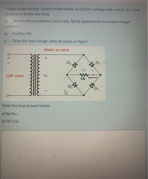
Unlike half-wave rectifiers, which discard the negative amplitude, the bridge rectifier preserves both polarities, classifying it as a full-wave rectifier. A key advantage of a bridge rectifier is that it eliminates the need for an expensive center-tapped transformer, thereby reducing both the size and cost of the circuit.
Full wave bridge rectifier is formed by connecting four diodes together in such a way that their arms form a bridge, hence the name bridge rectifier. In bridge rectifier, volatge can be applied to the diode bridge through a transformer or directly through the AC signal without the transformer. Here we are using 6-0-6 center tapped transformer

How to Make a Bridge Rectifier Circuit Circuit Diagram
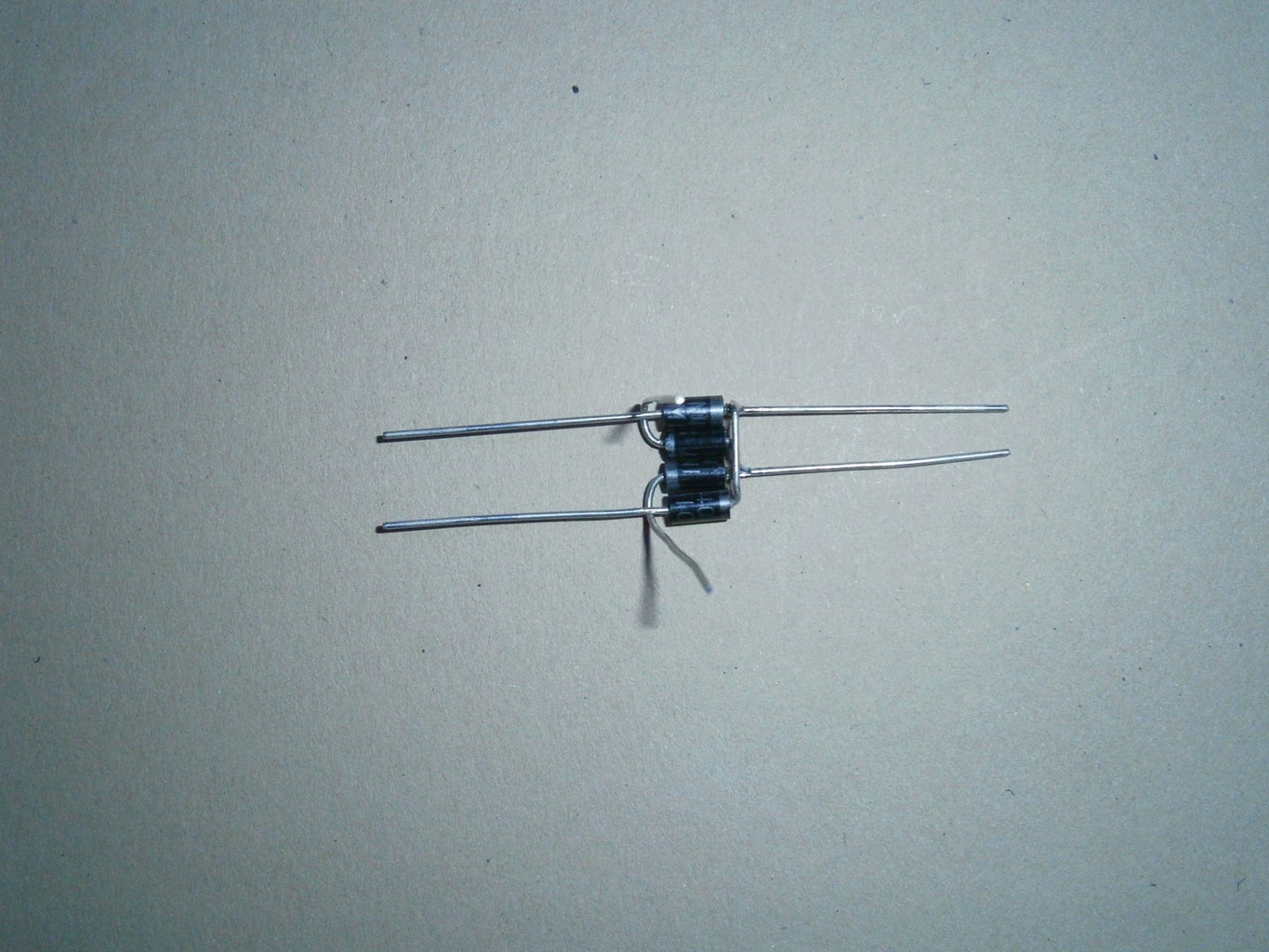
The Rectifier Diode. The diode bridge rectifier circuit is a very simple circuit made up of just four rectifier diodes connected in a square shape. A diode allows current to flow in one direction only (from the anode and to the cathode), which makes it perfect for converting from AC to DC.