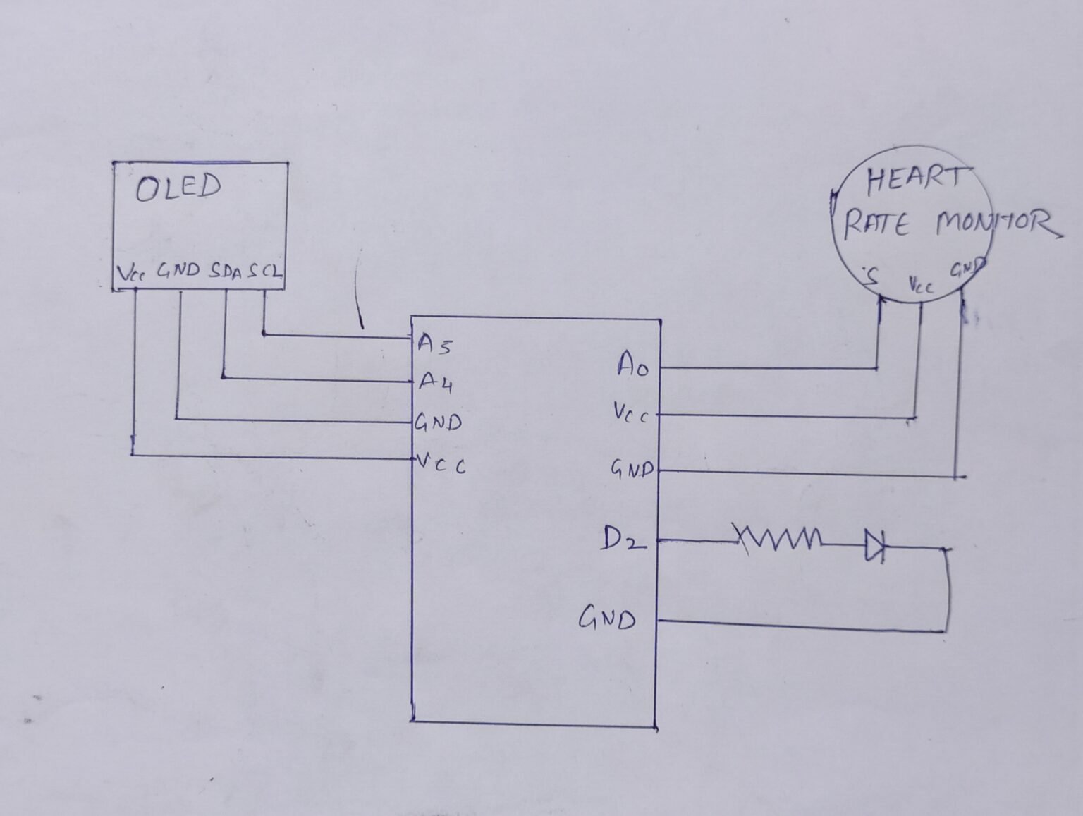
How to make Heart Rate Monitor Circuit Diagram The MAX30102 heart rate and oxygen sensor operates based on the principle of light absorption by blood in tissues and blood vessels. MAX30102 utilizes infrared (IR) and red light reflection technology to measure the oxygen saturation (SpO2) and heart rate (HR) of the user.
That's it, and you have successfully installed the library for heart rate sensor MAX30100 in your Arduino IDE. Arduino Code for Heart Rate Monitoring. The following code allows you to measure the heart rate in bpm and SpO2 in percentage using MAX30100 or MAX30102 pulse oximetry sensor. You can see the results on a serial monitor and a 16×2 LCD. This project aims to build a compact, DIY heart rate and oxygen saturation monitor using the MAX30100 sensor, an Arduino, and a 16x2 LCD. The MAX30100 is a pulse oximeter and heart-rate sensor, which works by shining infrared and red light through the skin to detect changes in blood oxygen levels and heartbeats. How It Works
![[PDF] Design of an Infrared based Blood Oxygen Saturation and Heart ... Circuit Diagram](https://d3i71xaburhd42.cloudfront.net/aaac1bbe96944018d040fec89dd64885d7cba9c0/36-Figure16-1.png)
Arduino Based Pulse Oximeter Health Monitoring Circuit Diagram
In this project we will make a device that can measure Blood Oxygen & Heart Rate using MAX30100 Pulse Oximeter & Arduino. The blood Oxygen Concentration termed as SpO2 is measured in Percentage and Heart Beat/Pulse Rate is measured in BPM. The MAX30100 is a Pulse Oximetry and heart rate monitor sensor solution. The heart of this DIY heart health monitor is the MAX30105 sensor, which is specially designed to measure heart rate and SpO2 (blood oxygen saturation). This sensor uses photo plethysmography (PPG) to detect changes in blood volume by shining LED light (red, infrared, and green) through your skin and measuring how much light is absorbed. DIY heart rate monitor and pulse oximeter using MAX30100 Pulse Oximeter Heart Rate Sensor Module. May 2, 2021

In this DIY project, we will try to make a Smart Health Monitoring Device that can measure SpO2 (percentage of oxygen in the blood) and heart rate. Athletes can use this wearable device to monitor their heart rate and blood oxygen levels during a workout. The best part of this project is that you can connect this device to an app that
Smart Blood Oxygen And Heart Rate Monitor With Automatic Data Saving System Circuit Diagram
In this project, I will guide you in creating a simple health-monitoring device. That measures heart rate and oxygen saturation (SpO2) and displays the data on an I2C LCD screen. By simply placing your finger on the sensor, the device will show your heart rate and SpO2. A non-invasive medical device that utilizes spectrophotometry to measure the oxygen saturation of circulating arterial blood in an individual by determining the percentage of oxygenated haemoglobin pulsating through a network of blood capillaries by way of a sensor attached typically to a finger. This sensor used to measure BPM( Heart beat per minute) and Spo2(Oxygen level in blood).
